Do an initial resistance check
The initial resistance check will help determine if there is excessive resistance in the plasma power supply.
All resistance values must be taken with the power cord disconnected and all internal plasma power supply wires attached. Do an internal inspection before you continue with this procedure.
- The type of multimeter you use significantly affects the results of the tests in this section. The resistance values in this manual are intended as a general reference point.
- If resistance values indicate a problem based on the range of values provided in this section, isolate the problem by removing wires attached to the resistance check points or component until you find the problem.
- After you locate and repair the problem, refer to Troubleshooting preparation to do a test of the plasma power supply for
correct operation.
Warning 

-
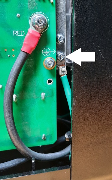
Measure the resistance across the input leads.
Pull back the red insulating covers, and measure the resistance where the wires connect to the center panel (or to the Electromagnetic Interference (EMI) Printed Circuit Board (PCB), for CE/CCC 1-phase models).
-
Measure the resistance from the input leads to ground to make sure that it
reads as open.
- For all models, make sure that the resistance from input to ground is >20 megaohms (MΩ).
- With the electric power disconnected and the power switch set to OFF (O), make sure that all circuits read as open.
- The electrical values shown are ±25%. However, this range is intended only for reference. Resistance values can vary widely depending on the type of multimeter and the polarity used to measure the readings.
-
Measure the output resistance for the values in the table.
The red nozzle wires connect to J15 (RED) on the power PCB. The white electrode wire connects to J18 (WHT).
Measure resistance from All models with torch disconnected Work lead (J23) to nozzle (J15) 200 kiloohms (kΩ) Work lead (J23) to electrode (J18) 16 kiloohms (kΩ) Electrode (J18) to nozzle (J15) 200 kiloohms (kΩ) Work lead (J23), nozzle (J15), and electrode (J18) to ground >20 megaohms (MΩ) 
-
Measure the resistance on each snubber resistor.


- Before you do recommended troubleshooting steps, make sure that you know the information in System diagrams and Overview.
- Before you purchase a major replacement component, make sure that you speak about the problem with Hypertherm® Technical Service or the nearest Hypertherm repair facility.