Grounding practices
When you set up an XPR® cutting system, make sure that you comply with all best practices for correctly grounding the system.
- Unless noted, for XPR cutting systems, use cables with a minimum gauge of 21.2 mm2 (4 AWG) (047031) for the Electromagnetic Interference (EMI) ground cables shown in the Example grounding diagram with a plasma cutting system.
- The cutting table is used for the common, or star, EMI ground point and should have threaded studs welded to the table with a copper bus bar mounted on them. A separate bus bar should be mounted on the gantry as close to each motor as possible. If there are motors at each end of the gantry, run a separate EMI ground cable from the far motor to the gantry bus bar. The gantry bus bar should have a separate, heavy EMI ground cable 21.2 mm2 (4 AWG; 047031) to the table bus bar. The EMI ground cables for the torch lifter and the Remote High Frequency (RHF) console or combined ignition/gas connect console must each run separately to the table ground bus.
- Inadequate grounding not only exposes operators to dangerous voltages, but inadequate grounding also increases the risk of equipment failure and unnecessary downtime. Ideally a ground should be zero ohms resistance, but field experience indicates under 1 ohm resistance is satisfactory for most applications. Hypertherm® recommends that you consult your national and local electrical codes to make sure that the grounding and shielding practices that you use comply with the requirements for your location.
- A ground rod (a Protective Earth (PE) ground) that meets all applicable national and local electric codes must be installed within 6 m (20 ft) of the cutting table. For XPR cutting systems, the PE ground must be connected to the cutting table ground bus bar using a minimum 21.2 mm2 (4 AWG) grounding cable (047031). Consult an electrician in your location to make sure that your grounding meets all national and local electric codes.
- For the most effective shielding, use the Hypertherm Computer Numerical Control (CNC) interface cables for Input/Output (I/O) signals, serial communication signals, between plasma cutting systems in multi-drop connections, and for interconnections between all components of the Hypertherm system.
- All hardware used in the ground system must be brass or copper. While you can use steel studs welded to the cutting table for mounting the ground bus, no other aluminum or steel hardware can be used in the ground system.
- Alternating Current (AC) power, PE, and service grounds must be connected to all equipment according to national and local codes.
- For a cutting system with a RHF console or combined ignition/gas connect console, the positive, negative, and pilot arc cables should be bundled together for as long a distance as possible. The torch lead, work cable, and the pilot arc (nozzle) cables may be run parallel to other wires or cables only if they are separated by at least 150 mm (6 inches). If possible, run power and signal cables in separate cable tracks.
- For a cutting system with a RHF console or combined ignition/gas connect console, Hypertherm recommends that you mount this console as close as possible to the torch. This console also must have a separate ground cable that connects directly to the cutting table ground bus bar.
- Each Hypertherm component, and any other CNC or motor drive cabinet or enclosure, must have a separate ground cable to the common (star) ground on the table. This includes the ignition/gas connect console, whether it is bolted to the plasma cutting system or to the cutting table.
- For XPR cutting systems, the coupler on the pilot arc and coolant hose assembly must be connected firmly to the gas connect console and TorchConnect™ console collars. Make sure to tighten the clamp. The collar on the torch lead must be connected firmly to the torch sleeve. Make sure to tighten the clamp. Connect a ground cable (10 AWG) to the flat terminal on the torch mounting sleeve.
- The torch holder and the torch breakaway mechanism – the part mounted to the lifter, not the part mounted to the torch – must be connected to the stationary part of the lifter with copper braid at least 12.7 mm (0.5 inches) wide. A separate cable must run from the lifter to the gantry ground bus bar. The valve assembly should also have a separate ground connection to the gantry ground bus bar.
- If the gantry runs on rails that are not welded to the table, then each rail must be connected with a ground cable from the end of the rail to the table. The rail ground cables connect directly to the table and do not need to connect to the table ground bus bar.
- If you are installing a voltage divider Printed Circuit Board (PCB), mount it as closely as possible to where the arc voltage is sampled. One recommended location is inside the plasma power supply enclosure. If a Hypertherm voltage divider PCB is used, the output signal is isolated from all other circuits. The processed signal should be run in twisted shielded cable (Belden® 1800F or equivalent). Use a cable with a braided shield, not a foil shield. Connect the shield to the chassis of the plasma cutting system and leave it unconnected at the other end.
- All other signals (analog, digital, serial, and encoder) should run in twisted pairs inside a shielded cable. Connectors on these cables should have a metal housing. The shield, not the drain, should be connected to the metal housing of the connector at each end of the cable. Never run the shield or the drain through the connector on any of the pins.
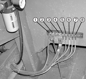
| 1 | Gantry ground bus |
|---|---|
| 2 | Ground rod |
| 3 | Plasma cutting system work cable (+) |
| 4 | Gas connect console |
| 5 | CNC enclosure |
| 6 | Torch holder |
| 7 | Plasma cutting system chassis |
| 8 | TorchConnect console |
| Cooler, if applicable (not shown) |
The following picture shows an example of a gantry ground bus. It is bolted to the gantry, close to the motor. All of the individual ground cables from the components mounted on the gantry connect to the bus. A single heavy cable then connects the gantry ground bus to the table ground bus.
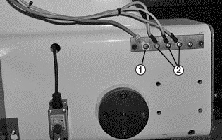
| 1 | Cable to the cutting table ground bus |
|---|---|
| 2 | Ground cables from components on the gantry |