Troubleshooting for a plasma power supply or torch communication fault (0-98-2)
An 0-98-2 fault code identifies a communication failure between the torch and the plasma power supply.
When this fault occurs, the SmartSYNC® torch is
not sending data to the plasma power supply, so the system cannot collect data about
the Hypertherm® cartridge. The problem can be
with the Hypertherm cartridge or with the
SmartSYNC torch. There can be a problem
with:
- The Printed Circuit Board (PCB) in the torch
- The torch lead
- The quick-disconnect receptacle
- The torch communication circuitry on the PCB in the plasma power supply
Fault codes and fault LEDs
| Fault code | Fault LEDs | Torch LED | Description | Stops the system from operating? |
|---|---|---|---|---|
| 0-98-2 |

ON |

Yellow |
A communication failure occurred between the torch and the plasma power supply. | No. You can continue to cut or gouge, but you must set the output current (A) and the operating mode manually. |
Corrective action for the plasma power supply (0-98-2)
-
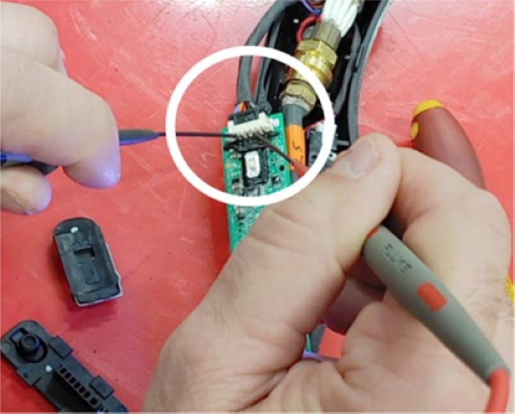
In the quick-disconnect receptacle on the front of the plasma power supply, measure
the voltage between pin 5 (blue wire) and pin 7 (orange wire).

Corrective action for the torch (0-98-2)
-
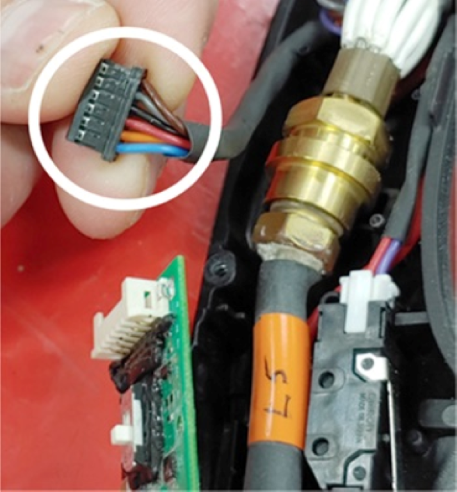
At the torch lead receptacle on the torch PCB, measure the voltage between pin 3 (black
wire) and pin 5 (orange wire).
Keep the wires from the torch connected, and measure the voltage at the rear of the receptacle, as shown.
-
Do a check for continuity between the torch and the plasma power
supply:
- Do a check for continuity between pin 1 on the torch PCB (brown wire) and pin 7 at J19 on the power PCB.
- Do a check for continuity between pin 2 on the torch PCB (gray wire) and pin 8 at J19 on the power PCB.
- If there is continuity between the pins, continue with step 12.
- If there is not continuity between the pins, continue with the next step.

1 Pin 1 and pin 2 on torch PCB 2 Pin 7 and pin 8 on power PCB -
Do a check for continuity on the torch:
- Do a check for continuity between pin 1 on the torch PCB (brown wire) and pin 9 in the torch connector.
- Do a check for continuity between pin 2 on the torch PCB (gray wire) and pin 10 in the torch connector.
- If there is continuity between the pins, continue with step 10.
- If there is not continuity between the pins, replace the torch lead.

-
Disconnect the torch lead connector from the torch PCB.