The Torch Cap fault Light Emitting Diode (LED) illuminates when the
torch or Hypertherm® cartridge is not ready to cut or is not able to cut.
Fault codes and fault LEDs
| Fault code |
Fault LEDs |
Torch LED |
Description |
Stops the system from operating? |
| None |

ON
|

Yellow
|
The Hypertherm cartridge was off, the torch was disconnected, or the
torch was in the yellow lock (X) position during a
restart. |
Yes |
Corrective action for the Hypertherm cartridge and torch
-
Move the torch-lock switch to the green "ready to fire" position.
This fault can show when you do a restart while the torch-lock switch
is in the yellow lock (X) position.
-
Remove the Hypertherm cartridge, and reinstall it correctly.
-
Reconnect the torch to the plasma power supply, and do a quick
restart.
- Optional::
Machine torch: Lock and unlock the torch, or do a quick restart.
This fault can be caused by removing the Hypertherm cartridge without first
setting the torch-lock switch to the yellow lock position or setting
the power switch to OFF (O).
- Optional::
Mini machine torch: Do a quick restart.
This fault can be caused by removing the Hypertherm cartridge without first
setting the power switch to OFF (O).
-
If possible, do a test with a different torch that is known to work
correctly.
-
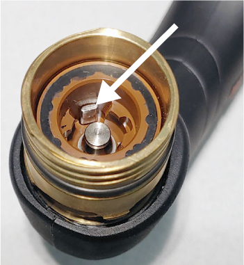
Push down the plunger in the torch head and then release.
-
Does the plunger move freely and go back to its start position?
OptionDescription
| If yes... |
Continue with the next procedure. |
| If no... |
Replace the torch body. |
Corrective action for the torch cap sensor in the torch and torch
lead
-
Disconnect the torch from the plasma power supply.
-
Make sure that a Hypertherm
cartridge is correctly installed on the torch and is not too loose or
too tight.
-
Make sure that the torch is set to the green "ready to fire"
position.
-
Measure the resistance between pin 5 and pin 7 in the torch
connector.
-
Is the resistance very low?
OptionDescription
| If yes... |
Continue with the next step. |
| If no... |
The cap-sensor switch in the torch is open. Continue with
step 9. |
-
Set the torch to the yellow lock (X) position.
-
Measure the resistance between pin 5 and pin 7 in the torch connector
again.
-
Is the resistance open?
-
Do a check for continuity on the torch wires:
-
Remove the left side of the torch shell.
-
Do a check for continuity between the blue wire and pin 5 (BLU)
in the torch connector.
-
Do a check for continuity between the orange wire and pin 7
(ORG) in the torch connector.
-
Do both torch wires have continuity?
OptionDescription
| If yes... |
Replace the cap-sensor switch. |
| If no... |
Replace the torch lead. |
Corrective action for the torch cap sensor in the plasma power supply
-
Set
the power switch to OFF (O), and disconnect the power cord from the power
source.
-
Remove the plasma
power supply handle and cover.
-
Remove the
component barrier.
-
Do a check for continuity on the torch receptacle.
-
Does each torch receptacle wire have continuity?
OptionDescription
| If yes... |
Continue with the next step. |
| If no... |
Replace the torch receptacle. |
-
Reconnect the torch to the plasma power supply.
-
Make sure that the Hypertherm
cartridge is installed correctly on the torch.
-
Make sure that the torch is set to the green "ready to fire"
position.
-
Measure the resistance between pin 1 and pin 2 at J19 on the power
Printed Circuit Board (PCB).
-
Is the resistance very low, approximately 1 ohm (Ω) or less?
OptionDescription
| If yes... |
If you cannot find or
correct the problem, a qualified service technician must repair the system. Speak to your
distributor or authorized repair facility. |
| If no... |
The cap-sensor switch circuit is open. Replace the power
PCB. |