Troubleshooting for an RF communication fault (0-98-1)
An 0-98-1 fault code identifies a Radio Frequency (RF) communication failure between the Hypertherm® cartridge and the torch.
When this fault occurs, the Hypertherm cartridge is not sending data to the system, so the system cannot collect data about the Hypertherm cartridge. The problem can be with the Hypertherm cartridge or with the SmartSYNC® torch.
Fault codes and fault LEDs
| Fault code | Fault LEDs | Torch LED | Description | Stops the system from operating? |
|---|---|---|---|---|
| 0-98-1 |

ON |

Yellow |
An RF communication failure occurred between the Hypertherm cartridge and the torch. | No. You can continue to cut or gouge, but you must set the output current (A) and the operating mode manually. |
Corrective action for the Hypertherm cartridge (0-98-1)
-
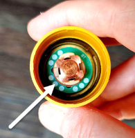
Make sure that the green ring inside the Hypertherm cartridge is not broken.
Corrective action for the torch (0-98-1)
-
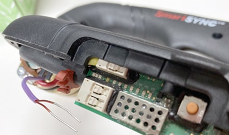
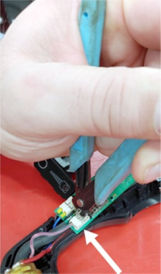
Disconnect the two antenna wires from the torch PCB.
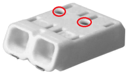
 Note:
Note:If the antenna connectors look like the one shown here, insert an object such as a paper clip into the holes to release the antenna wires.
-
With the antenna wires disconnected, measure the resistance of the
antenna coil in the connector on the torch PCB.
Is the resistance less than 1 ohm (Ω)?
Option Description If yes... the antenna wires have possible damage. Replace the torch body. If no... the antenna on the torch PCB has possible damage. Replace the torch PCB.