Attach the front panel

Figure 1. Front panel parts
Exploded view of the front panel on the plasma power supply.
1 1-phase power switch 7 Torch receptacle nut
2 3-phase power switch 8 Transformer wire
3 Display Printed Circuit Board (PCB) ribbon cable 9 Torch receptacle plastic washer
4 Work lead screw and washers 10 Torch receptacle and screws
5 Gas supply hose 90° fitting 11 Work lead
6 Brass torch fitting
  1. Attach the screw and washers to secure the work lead wire to the work lead receptacle.

    Tighten to 10.2 N∙m (90 lbf·in).

  2. Put the torch receptacle into place in the front panel so the red wires are at the top.
  3. Screw the torch receptacle to the front panel.

    If there are only 2 screws, mount them at opposite corners. Tighten to 1.7 N∙m (15 lbf·in).

  4. Place the brass torch fitting into the torch receptacle.

    The fitting slides in from the front of the connector.

  5. Slide the large plastic washer over the brass torch fitting.
  6. Slide the transformer wire ring terminal over the brass torch fitting.
  7. Screw the nut onto the brass torch fitting.

    Tighten to 9.2 N∙m (80 lbf·in).

  8. Push-to-connect the gas supply hose 90° fitting to the brass torch fitting.
  9. Attach the power switch to the front panel:
    • 1-phase models: Attach the power switch assembly to the front panel using 2 screws. Tighten to 1.1 N∙m (10 lbf·in).
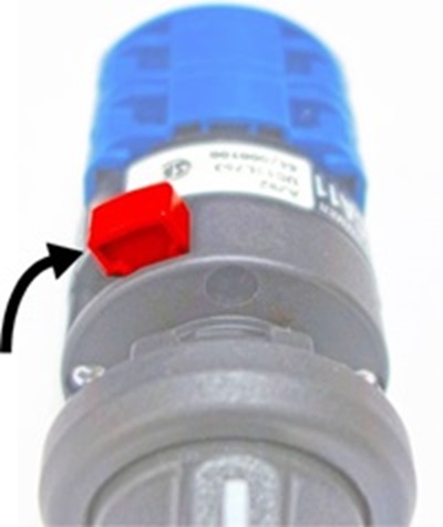
    • 3-phase models: Set the knob to the ON (I) position. Press the switch assembly onto the shaft of the power switch knob. The red latch should be in the "LOCK" position as shown. Press until the assembly clicks and is securely held in place.Image of the power switch knob.
  10. Set the front panel into place so the tabs at the bottom snap into place.

    Make sure no wires are pinched as you put the panel back in place.

  11. Complete the following procedures:
    1. Install the plasma power supply cover and handle.
    2. Reconnect the torch and the work lead to the front panel.
    3. Reconnect the gas supply and the power cord.