A 3-00-0 fault indicates that the Direct Current (DC) bus
voltage (VBUS) is out of range.
Fault codes and fault LEDs
Fault code
Fault LEDs
Torch LED
Description
Stops the system from operating?
3-00-0
ON
Red
The DC bus voltage
(VBUS) is out of range.
Yes
Corrective action for VBUS faults using test points (3-00-0)
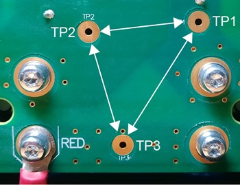
Do a test of the power Printed Circuit Board (PCB) to make sure
that the circuits are balanced. Use the test points on the power
PCB to do the test. There are labels
on the rear of the power PCB for the test
points (TP1, TP2, TP3).
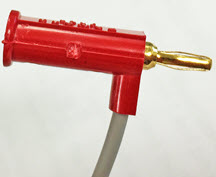
Use miniature banana plugs to connect to the test points on the power
PCB as shown in this procedure. Refer
to Required test equipment.
If miniature banana plugs are not available, use small test clips that you can
attach to the copper contacts in the test point openings on the power
PCB.
Notice
DO NOT CONNECT -VBUS TO GROUND
Do not connect -VBUS (TP1) to ground. This can cause damage to the
plasma power supply so that it becomes unserviceable.
Notice
SHORT CIRCUIT BETWEEN BUS AND HEATSINK IS POSSIBLE
Do not use a multimeter with test leads for this test. This can cause a
short-circuit between the BUS and the heatsink. Use mini-banana plugs for this
test, and attach them to the test point (TP) openings in the power
PCB.
Set the power switch to
OFF (O), disconnect the power cord from the power source, and disconnect the gas
supply.
Remove the plasma
power supply handle and cover.
Remove the
component barrier.
Reconnect the electrical power, but keep the power switch set to OFF
(O).
Measure the voltage between the TP1 and TP2 test points.
Put the mini-banana plugs at TP1 and TP2 on the power
PCB.
Set the power switch to ON (I).
Make sure that the voltage is approximately:
280 VDC/340 VDC for 200 V/240 V 1-phase models
560 VDC for 400 V CE/CCC 3-phase models
670 VDC for 480 V CSA 3-phase models
Measure the voltage between the TP1 and TP3 test points.
Set the power switch to OFF (O).
Move the mini-banana plugs to TP1 and TP3 on the power
PCB.
Set the power switch to ON (I).
Make sure that the value is approximately one-half of the value
from step 5:
140 VDC/170 VDC for 200 V/240 V 1-phase models
280 VDC for 400 V CE/CCC 3-phase models
335 VDC for 480 V CSA 3-phase models
All values can be ±10%.
Measure the voltage between the TP2 and TP3 test points.
Set the power switch to OFF (O).
Move the mini-banana plugs to TP2 and TP3 on the power
PCB.
Set the power switch to ON (I).
Make sure that the value is approximately one-half of the value
from step 5:
140 VDC/170 VDC for 200 V/240 V 1-phase models
280 VDC for 400 V CE/CCC 3-phase models
335 VDC for 480 V CSA 3-phase models
Are the voltages in step 6 and step
7
approximately equal, and is the capacitor resistance in the correct
range?
OptionDescription
If yes...
If you cannot find or
correct the problem, a qualified service technician must repair the system. Speak to your
distributor or authorized repair facility.
If no...
If the voltage values are different by more than 30 V, and
if the capacitor resistance is out of range, replace the power
PCB. Refer to Remove the power PCB.
Corrective action for VBUS faults using the capacitor terminals
(3-00-0)
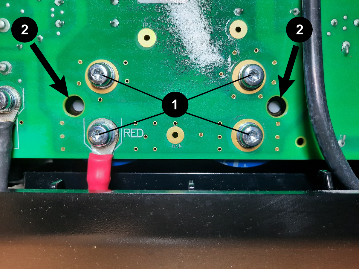
Do a test of the power PCB to make sure
that the circuits are balanced. Use the capacitor screws to do the test. There
are labels on the rear of the power PCB
for the positive (+) and negative (-) capacitor terminals.
Warning
ELECTRIC SHOCK CAN
KILL
Let the system release internal
voltages before you touch the capacitors. The
capacitors can hold a charge for several minutes
after the system is set to OFF.
Wait approximately 10 minutes for internal voltages to
discharge.
Loosen the capacitor screws enough that you can disconnect the
capacitors from the power PCB.
Measure the resistance across the capacitors, and make sure that the
resistance is approximately:
13.5 kiloohms (kΩ) for 1-phase models
18 kiloohms (kΩ) for 3-phase models
Do a visual inspection of the capacitors.
Replace the capacitors if you do not see white dots in the vent holes
next to the capacitors, as shown.