Install the power PCB
Refer to this image as you do the steps in this procedure.

| 1 | Power switch connections (J1 and J2 for 1-phase; J1, J2, and J4 for 3-phase) | 8 | Power transformer primary – red |
| 2 | Dual red nozzle wires from torch receptacle (J15) | 9 | Power Factor Correction (PFC) inductor – red (J5) |
| 3 | White electrode wire from torch socket (J18) | 10 | PFC inductor – black (J4 for 1-phase; J26 for 3-phase) |
| 4 | Power transformer secondary – black (J14) | 11 | Output inductor – yellow (J13) |
| 5 | Power transformer secondary – red (J12) | 12 | Work lead wire (J23) |
| 6 | Power transformer primary – black (J6) | 13 | PFC inductor |
| 7 | Power switch connections (J1 and J2 for 1-phase; J1, J2, and J4 for 3-phase) | 14 | Power transformer |
| Notice | |
|---|---|
-
1-phase models: Plug the 2-wire connector from the power switch
assembly into J10 on the power PCB.
Note:
The J10 connection is for the trip coil on the power switch. There is no trip coil on 3-phase models.
Figure 2. J10 connector on the 1-phase power PCB 
-
Put the power PCB into position inside
the plasma power supply.
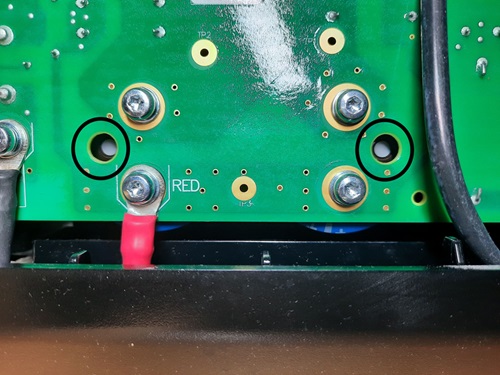
Note:
Make sure that the white polarity dot on each capacitor aligns with the viewing hole on the power PCB.
-
Slowly tighten to 2.3 N∙m (20 lbf·in) the IGBT screws and the rectifier screw
in the sequence shown here.
Figure 3. 1-phase power PCB sequence for tightening the screws 
Figure 4. 3-phase power PCB sequence for tightening the screws 
-
Make the following connections to the power PCB.
Component Connector on power PCB Connector type Solenoid valve assembly J8 8-pin Fan J7 4-pin RS-485 serial interface J11 5-pin Machine interface port J21 4-pin Voltage divider PCB J17 2-pin Torch receptacle J19 10-pin Display PCB J3 Ribbon cable Figure 5. More component connections on the power PCB 